
In the first part we learned the logic and components of the system and we configured the central component – Raspberry PI. In today’s post we’ll add some sensors and relays and we’ll integrate them with the central server via wi-fi, using the ESP8266 wireless modules. Let’s begin!
Step one – Install and configure ESP8266 wireless module
I’ve used so far in my projects two types of wireless modules and namely the ESP8266 ESP-01 and ESP8266 ESP-12.
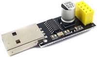
To configure the first type of module, you will need a special USB adapter that is looking like the one bellow.
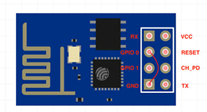
In order to set the ESP8266 ESP-01 in write mode, you have to make a strap between GPI0 and GND (check the picture bellow). Then insert the wireless module in the adapter and connect it via usb in your laptop/desktop computer.
I’m using in my projects ESPEasy as firmware, it’s a great software with a nice interface and very easy to configure and use. You can get it from this link https://github.com/letscontrolit/ESPEasy/releases.
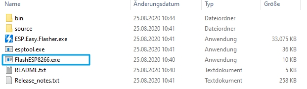
After you download it, unpack it and run this executable.
Check your COM port of the USB and select firmware version. We’ve used in this case ESP_Easy_mega-20200812_normal_ESP8266_1M.bin.
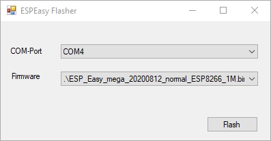
After you press the Flash button, a new window will open and you can see here the status of writing the firmware.
Remove the ESP8266 module from the adapter once the Flash is written. Then connect the desired sensor to it and power it on.
In Windows System, search for ESP_Easy_0 wi-fi network and connect to it using the defult password “configesp”.
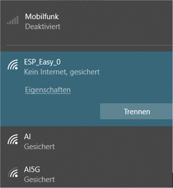
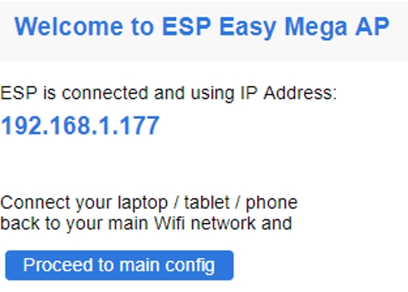
Once the wi-fi connection is estabilished, open a browser and add the address http://192.168.4.1 to access the interface of the ESP8266. On this page, select your SSID, add the password and press connect.
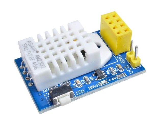
Step two – Configure ESP_Easy with temperature sensor
In this setup we’ll use a module ESP8266 E-01 together with a temperature sensor model DHT22. So connect them each other and then access the IP address of the ESP module via a browser to start the configuration.
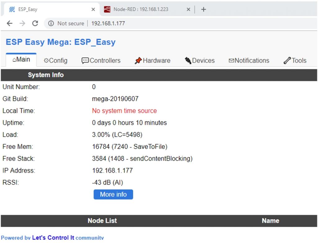
On the Main tab are the System Info (firmware version, uptime, IP address,etc.).
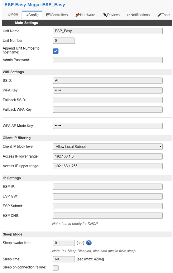
On the Config tab you can change the Name of the ESP module, the Wifi settings and the IP settings of the ESP. In case you want to use the Deep Sleep feature, you should do it also here and configure these 2 parameters:
Sleep Awake Time = The time the ESP module will be alive after recovering from Deep Sleep
Sleep Time = The time the ESP module will sleep
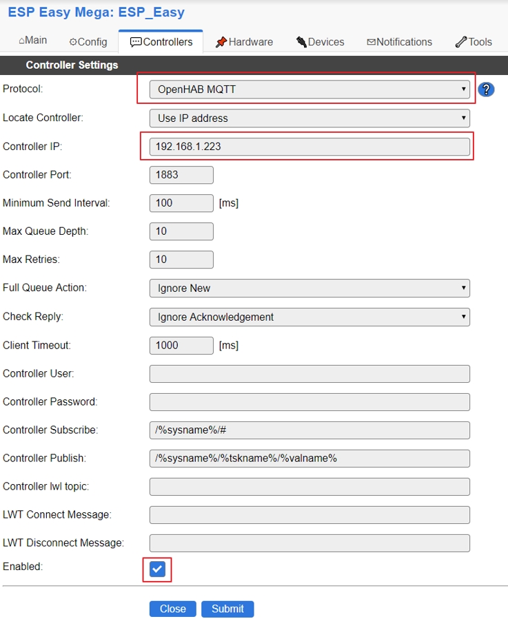
On the Controllers tab, set OpenHAB MQTT as protocol, insert the IP address of the controller (Raspberry PI in our case) and at the end check Enabled.
Set the Device as Environment – DHT11/12/22 on the Devices tab. Then set a name and check Enabled. For the sensor’s GPIO set GPIO-2 (D4) and DHT22 for the model. Then check Send to Controller.
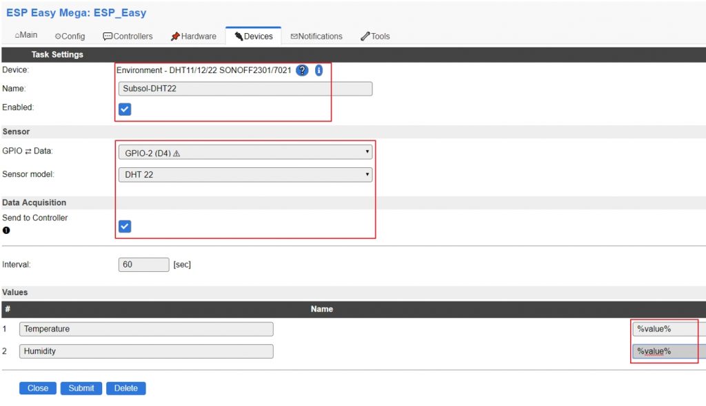
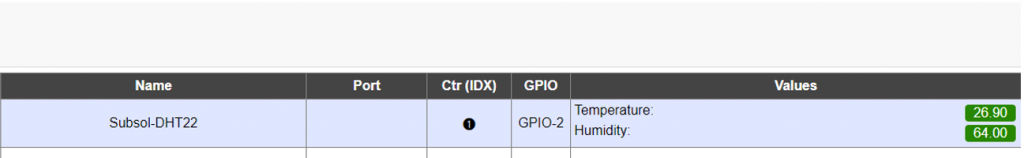
After pressing Submit, if everything is working fine, the values measured by the sensor can be noticed already.
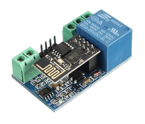
Step three – Configure ESP_Easy with Relays
At this step we’ll configure an integrated module with ESP8266 and a relay. This is how it looks.
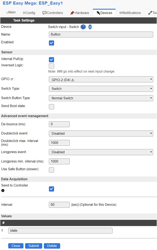
Connect to the IP Addres of the ESP_Easy and on the Devices tab select Switch input – switch as Device, then add a name and check Enabled. For the Sensor make these settings GPIO = GPIO-2(D4), Switch Type = Switch and Switch Button Type = Normal Switch. Then check Send to Controller and set the Values number 1 as state.
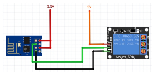
If you don’t have an integrated module like the one above, use this wiring to connect the relay to the ESP module.
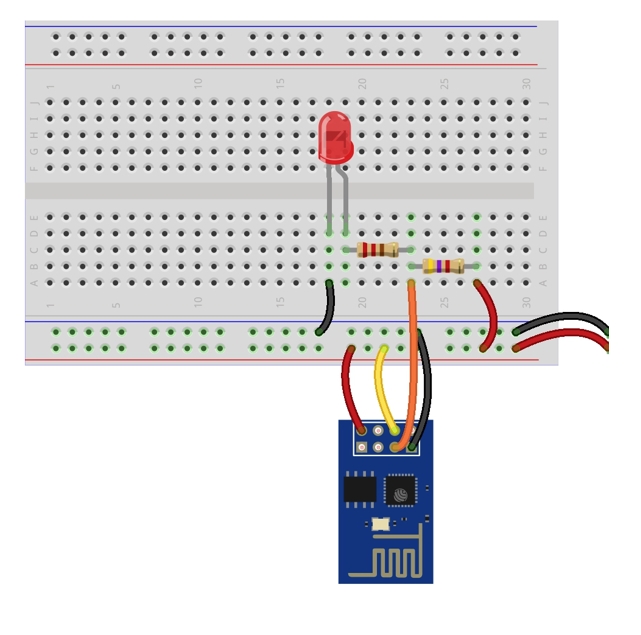
Instead of a relay, you can connect also a LED using the same configuration. In this case here is the wiring:
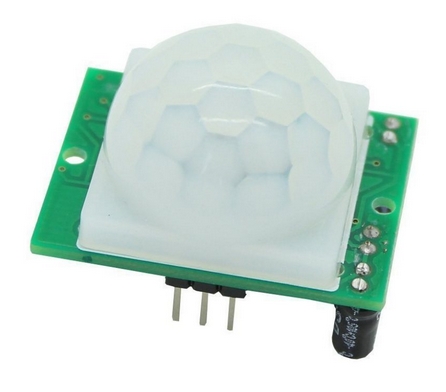
Step four – Configure ESP_Easy with a PIR Sensor
In this step we’ll configure a module ESP8266 with a PIR(passive infrared ) sensor.
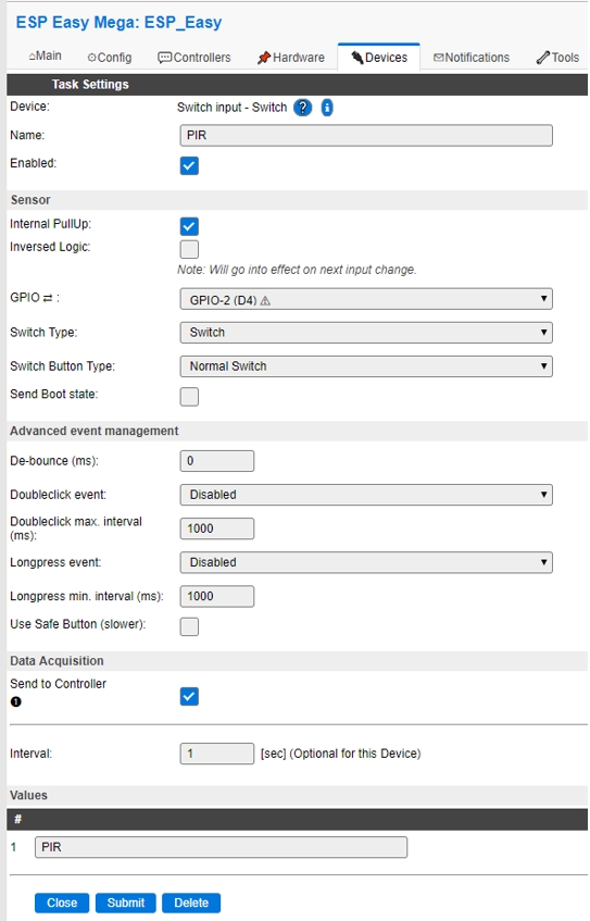
Connect to the IP Addres of the ESP_Easy and on the Devices tab select Switch input – switch as Device, then add a name and check Enabled. For the sensor make these settings GPIO = GPIO-2(D4), Switch Type = Switch and Switch Button Type = Normal Switch. Then check Send to Controller and set the Values number 1 as PIR.
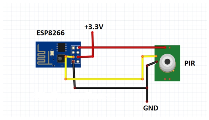
Here is the wiring for this configuration:
Conclusion
We learned in this post how to connect different types of sensors and how to configure them on ESP-Easy. In the next post we’ll see how to configure these sensors and relays in node-red. So stay around if you want to learn more.